Simulation / FEA / Automotive / Creo / ANSYS
Formula SAE Brake Rotor Analysis
Used thermal and structural simulation to evaluate brake rotor materials, temperature response, and geometry for a student race vehicle.
- YEAR
- 2025
- STATUS
- Complete
Objective
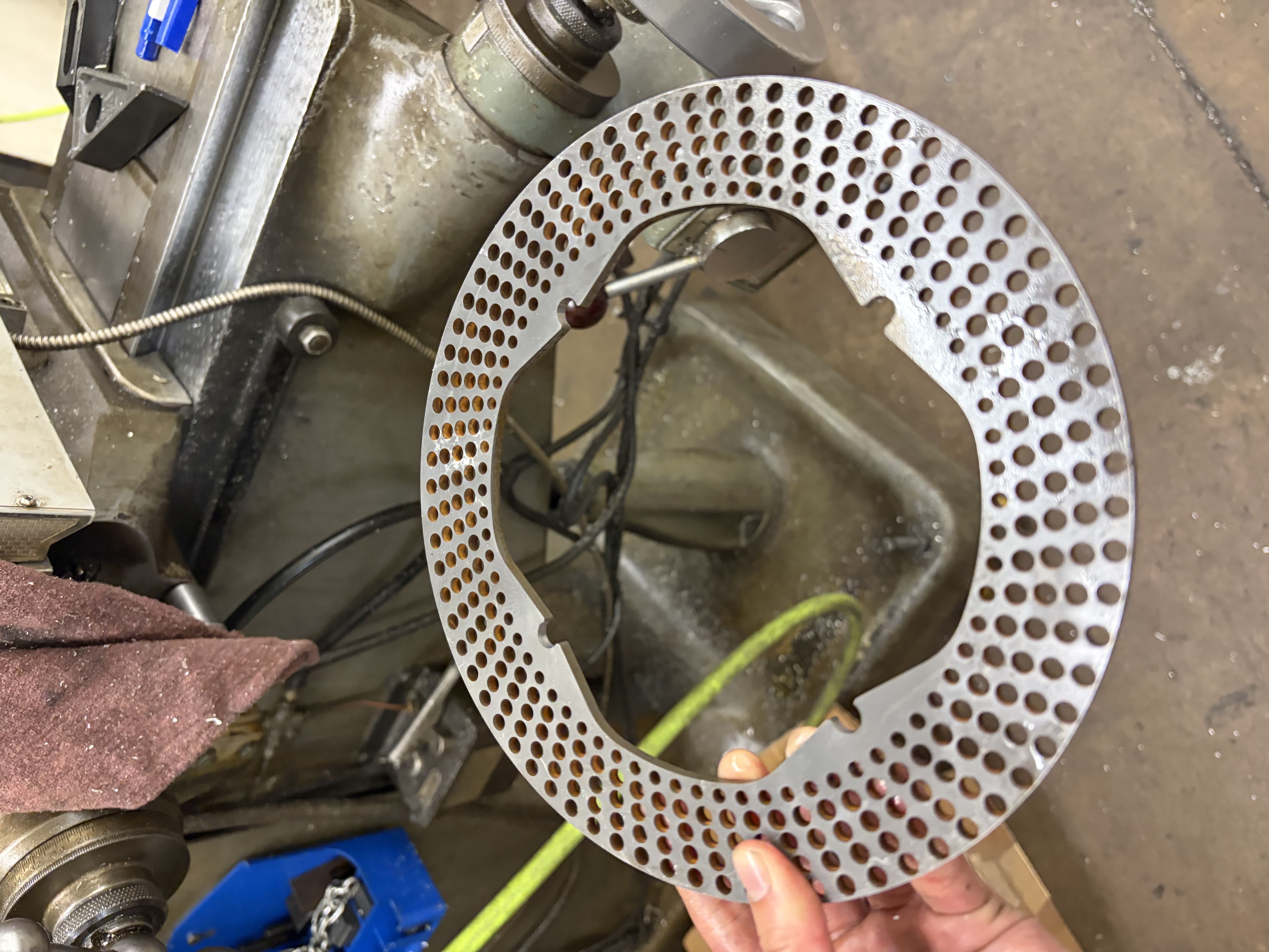
Design and evaluate front and rear brake rotors for a Formula SAE vehicle capable of supporting the braking-system requirements of competition. The primary performance case was the Formula SAE brake test, in which the vehicle must accelerate to at least 30 mph and generate enough braking force to lock all four wheels until the car reaches a complete stop. The rotor design therefore needed to withstand the associated braking torque and elevated operating temperatures without excessive stress or deformation.
Requirements
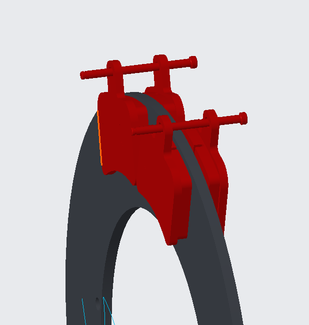
The rotor geometry was constrained by the existing wheel, hub, caliper, and brake-pad interfaces, limiting the available outer diameter, mounting geometry, thickness, and usable friction surface. The design also had to provide sufficient structural margin under the torque required for four-wheel lockup while minimizing rotating and unsprung mass. Because repeated braking can significantly increase rotor temperature, material properties at elevated temperatures were considered rather than relying only on room-temperature values.
For the competition brake test, the complete vehicle must reach at least 30 mph before braking, lock all four wheels, and maintain lockup until coming to a complete stop. These system-level requirements were translated into rotor-level load cases used to evaluate candidate geometries and materials.
Method
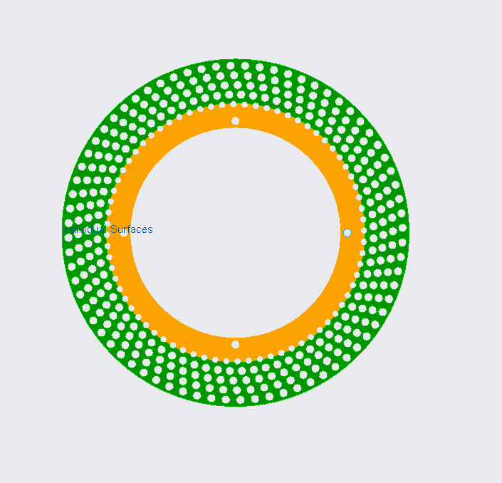
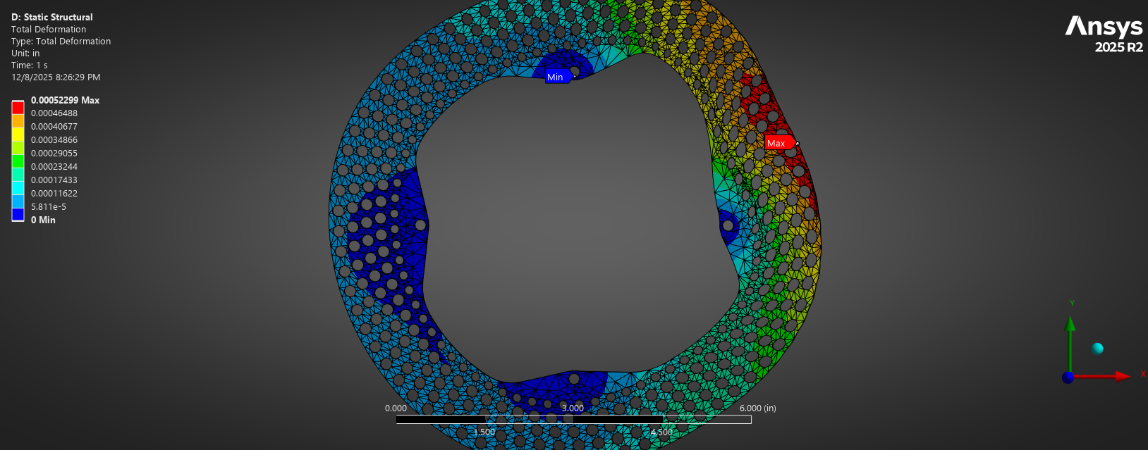
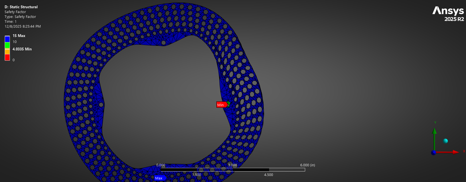
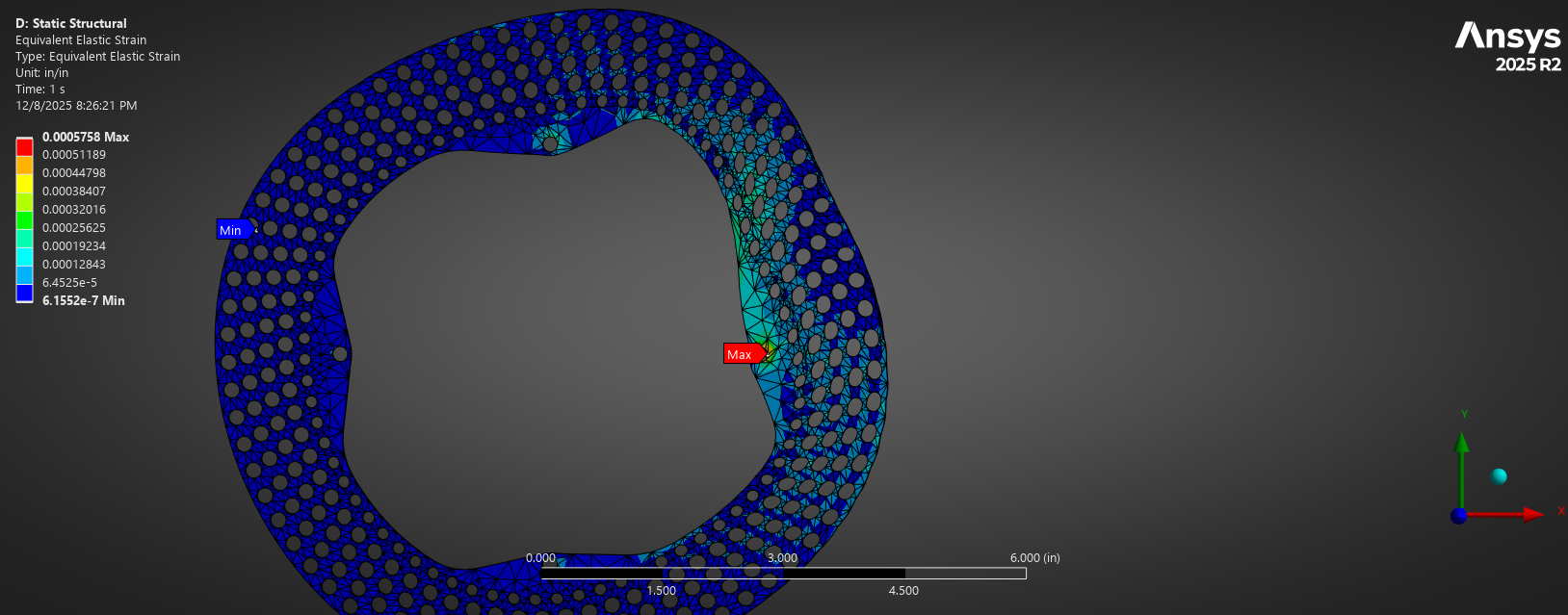
I developed the front and rear rotor geometry in Creo and compared AR500 and G3000 as candidate materials. Temperature-dependent material properties were incorporated into the analysis so that structural performance could be evaluated under more representative operating conditions. Braking torque and elevated-temperature load cases were then applied in ANSYS Mechanical to compare von Mises stress, deformation, and factor of safety between material and geometry configurations.
The analysis was used as a comparative design tool rather than a final certification model. Boundary conditions, material-property assumptions, contact behavior, and mesh refinement were documented so that the model could be repeated and improved as better vehicle and test data became available.
Design Considerations
Material removal was used to reduce rotor mass while preserving the friction surface and load paths required to transmit braking torque from the pad interface to the hub. Each design iteration balanced competing objectives including strength, thermal exposure, mass reduction, pad contact area, manufacturability, and packaging within the existing brake assembly.
The comparison ultimately favored AR500 for the analyzed configuration because of the structural margin predicted by the model at elevated temperature. The result was treated as a design recommendation based on the simulated load cases rather than proof of real-world thermal or fatigue performance.
Key Learning
This project gave me practical experience translating a vehicle-level requirement into component-level engineering load cases. The most important lesson was that an FEA result is only as useful as the assumptions behind it. Boundary-condition selection, temperature-dependent material data, mesh refinement, and realistic loading all had a significant influence on the predicted rotor behavior.
It also reinforced the difference between simulation and validation. The analysis provided a useful basis for comparing designs and identifying high-stress regions, but physical braking and thermal testing would still be required to validate the rotor under actual vehicle operating conditions.